Introduction to Physical Infrastructure and Topology
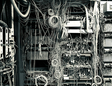 Managing a network without a clear, accurate map can feel like navigating a maze blindfolded. When you cannot see the physical connections between your hardware, even a minor change can lead to massive troubleshooting headaches or costly downtime. Whether you are scaling a data center or managing a corporate office, understanding the physical layout of a network is the foundation of a reliable IT environment.
This layout is more than just a picture of wires and boxes; it is the master blueprint that dictates how your data moves, how quickly you can recover from failures, and how efficiently your team can plan for future growth. By documenting your hardware’s true footprint—including racks, cabling paths, and port assignments—you create a single source of truth that bridges the gap between technical teams and facilities management.
In this guide, we will break down the essentials of building, documenting, and maintaining a robust infrastructure. We will explore how to choose the right topology, how to balance power and cooling constraints, and why a well-maintained managed network layout is the most valuable asset in your IT toolkit. From initial planning to automated lifecycle maintenance, we will show you how to turn your physical network into a clear, predictable, and scalable system.
Physical vs. Logical Topology Differences
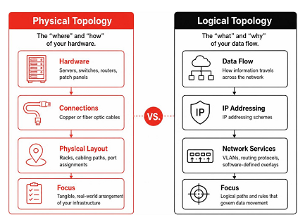
To master network design, one must first distinguish between the physical and the logical. The physical layout of a network refers to the tangible, real-world arrangement of your infrastructure. It encompasses every server, switch, router, patch panel, and the actual copper or fiber optic cables snaking through your ceilings and under your floors. It is the “where” and “how” of your hardware.
In contrast, the logical topology describes the “what” and “why” of your data flow. It focuses on how information travels across the network, including IP addressing schemes, VLANs, routing protocols, and software-defined overlays. While a physical diagram shows you which port on a switch a server is plugged into, a logical diagram shows you the path that a packet takes from a client to a database.
Confusion often arises when teams try to force both perspectives into a single diagram. Research in graph theory suggests that combining these views increases “edge crossings,” which are the strongest predictor of human reading errors. Instead, we recommend a layered approach. Use your physical documentation for hardware maintenance and capacity planning, and use your logical maps for traffic optimization and security policy design. When you need to bridge the two, use containment nesting—where logical subnets are represented as containers holding the physical devices within them—rather than drawing complex, overlapping lines.
Topological Frameworks in a Managed Network Layout
Choosing the right physical structure is a strategic decision that balances performance, cost, and fault tolerance.
When you invest in a professional managed network layout, you are essentially selecting the framework that best aligns with your business goals. For example, a small office may thrive on a simple star configuration, while a high-availability data center might require a full-mesh backbone to ensure zero downtime.
Engineering and Documenting a Managed Network Layout
Documentation is the difference between a resilient network and a house of cards. Engineering a layout requires more than just connecting devices; it requires a systematic approach to inventory and spatial planning.
Essential Components of a Managed Network Layout
A truly comprehensive physical map consists of several distinct layers:
Spatial Constraints, Power, and Cooling
Physical design is bound by the laws of physics. A 42U or 48U rack is not just a container; it is an ecosystem. When planning your layout, you must account for:
Deployment, Automation, and Lifecycle Maintenance Conclusion
The most common mistake in network management is treating the physical diagram as a “one-and-done” artifact. A diagram that is six months out of date is often worse than no diagram at all, as it provides a false sense of security.
Step-by-Step Layout Documentation and Verification
To keep your infrastructure documentation alive, follow these steps:
Modern Automation, AI Planning, and Maintenance Strategies
We are moving into an era where manual diagramming is being replaced by intelligent, automated systems. Research into the “Planogram” concept—which utilizes integer linear programming and reinforcement learning—shows that we can now optimize physical placements based on latency, power, and cooling constraints automatically.
By integrating your diagrams with your CMDB (Configuration Management Database) and change management tickets, you can ensure that every “move, add, or change” (MAC) is reflected in your documentation in real-time. For large-scale environments, we recommend a quarterly audit to reconcile the physical inventory with your digital maps.
Your physical network is a living, breathing entity. By treating your managed network layout as a continuous project rather than a static document, you ensure that your organization remains agile, secure, and ready for whatever growth comes next. When the unexpected occurs, you won’t be fumbling in the dark—you will have the clear, precise, and reliable roadmap you need to guide your team to success.